On the Wire
Table of Contents
- On the Wire
Overview
Help Evan next to city hall hack this gnome and retrieve the temperature value reported by the I2C device at address 0x3C. The temperature data is XOR-encrypted, so you'll need to work through each communication stage to uncover the necessary keys. Start with the unencrypted data being transmitted over the 1-wire protocol.
Introduction
Evan Booth
Hey, I'm Evan!
I like to build things.
All sorts of things.
If you aren't failing on some front, consider adjusting your difficulty settings.
So here's the deal - there are some seriously bizarre signals floating around this area.
Not your typical radio chatter or WiFi noise, but something… different.
I've been trying to make sense of the patterns, but it's like trying to build a robot hand out of a coffee maker - you need the right approach.
Think you can help me decode whatever weirdness is being transmitted out there?
You know what happens to electronics in extreme cold? They fail. All my builds, all my robots, all my weird coffee-maker contraptions—frozen solid. We can't let Frosty turn this place into a permanent deep freeze.
Hints
Hint 1: Protocols
Key concept - Clock vs. Data signals:
- Some protocols have separate clock and data lines (like SPI and I2C)
- For clocked protocols, you need to sample the data line at specific moments defined by the clock
- The clock signal tells you when to read the data signal
For 1-Wire (no separate clock):
- Information is encoded in pulse widths (how long the signal stays low or high)
- Different pulse widths represent different bit values
- Look for patterns in the timing between transitions
For SPI and I2C:
- Identify which line is the clock (SCL for I2C, SCK for SPI)
- Data is typically valid/stable when the clock is in a specific state (high or low)
- You need to detect clock edges (transitions) and sample data at those moments
Technical approach:
- Sort frames by timestamp
- Detect rising edges (0→1) and falling edges (1→0) on the clock line
- Sample the data line's value at each clock edge
Hint 2: Structure
What you're dealing with:
- You have access to WebSocket endpoints that stream digital signal data
- Each endpoint represents a physical wire in a hardware communication system
- The data comes as JSON frames with three properties: line (wire name), t (timestamp), and v (value: 0 or 1)
- The server continuously broadcasts signal data in a loop - you can connect at any time
- This is a multi-stage challenge where solving one stage reveals information needed for the next
Where to start:
- Connect to a WebSocket endpoint and observe the data format
- The server automatically sends data every few seconds - just wait and collect
- Look for documentation on the protocol types mentioned (1-Wire, SPI, I2C)
- Consider that hardware protocols encode information in the timing and sequence of signal transitions, not just the values themselves
- Consider capturing the WebSocket frames to a file so you can work offline
Hint 3: On Rails
Stage-by-stage approach:
- Connect to the captured wire files or endpoints for the relevant wires.
- Collect all frames for the transmission (buffer until inactivity or loop boundary).
- Identify protocol from wire names (e.g., dq → 1-Wire; mosi/sck → SPI; sda/scl → I2C).
- Decode the raw signal:
- Pulse-width protocols: locate falling→rising transitions and measure low-pulse width.
- Clocked protocols: detect clock edges and sample the data line at the specified sampling phase.
- Assemble bits into bytes taking the correct bit order (LSB vs MSB).
- Convert bytes to text (printable ASCII or hex as appropriate).
- Extract information from the decoded output — it contains the XOR key or other hints for the next stage.
- Repeat Stage 1 decoding to recover raw bytes (they will appear random).
- Apply XOR decryption using the key obtained from the previous stage.
- Inspect decrypted output for next-stage keys or target device information. - Multiple 7-bit device addresses share the same SDA/SCL lines. - START condition: SDA falls while SCL is high. STOP: SDA rises while SCL is high. - First byte of a transaction = (7-bit address << 1) | R/W. Extract address with address = first_byte >> 1. - Identify and decode every device's transactions; decrypt only the target device's payload. - Print bytes in hex and as ASCII (if printable) — hex patterns reveal structure. - Check printable ASCII range (0x20–0x7E) to spot valid text. - Verify endianness: swapping LSB/MSB will quickly break readable text. - For XOR keys, test short candidate keys and look for common English words. - If you connect mid-broadcast, wait for the next loop or detect a reset/loop marker before decoding. - Buffering heuristic: treat the stream complete after a short inactivity window (e.g., 500 ms) or after a full broadcast loop. - Sort frames by timestamp per wire and collapse consecutive identical levels before decoding to align with the physical waveform.
Hint 4: Garbage?
If your decoded data looks like gibberish:
- The data may be encrypted with XOR cipher
- XOR is a simple encryption:
encrypted_byte XOR key_byte = plaintext_byte - The same operation both encrypts and decrypts:
plaintext XOR key = encrypted,encrypted XOR key = plaintext
How XOR cipher works:
function xorDecrypt(encrypted, key) {
  let result = "";
  for (let i = 0; i < encrypted.length; i++) {
    const encryptedChar = encrypted.charCodeAt(i);
    const keyChar = key.charCodeAt(i % key.length);  // Key repeats
    result += String.fromCharCode(encryptedChar ^ keyChar);
  }
  return result;
}
Key characteristics:
- The key is typically short and repeats for the length of the message
- You need the correct key to decrypt (look for keys in previous stage messages)
- If you see readable words mixed with garbage, you might have the wrong key or bit order
Testing your decryption:
- Encrypted data will have random-looking byte values
- Decrypted data should be readable ASCII text
- Try different keys from messages you've already decoded
Hint 5: Bits and Bytes
Critical detail - Bit ordering varies by protocol:
MSB-first (Most Significant Bit first):
- SPI and I2C typically send the highest bit (bit 7) first
- When assembling bytes:
byte = (byte << 1) | bit_value - Start with an empty byte, shift left, add the new bit
LSB-first (Least Significant Bit first):
- 1-Wire and UART send the lowest bit (bit 0) first
- When assembling bytes:
byte |= bit_value << bit_position - Build the byte from bit 0 to bit 7
I2C specific considerations:
- Every 9th bit is an ACK (acknowledgment) bit - ignore these when decoding data
- The first byte in each transaction is the device address (7 bits) plus a R/W bit
- You may need to filter for specific device addresses
Converting bytes to text:
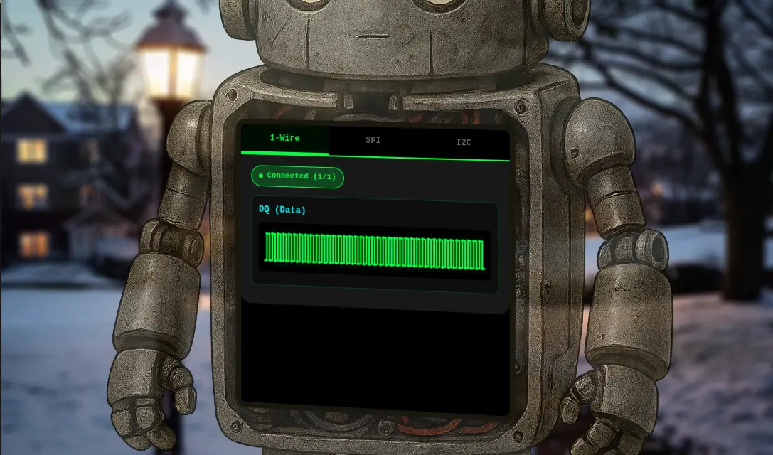
Analysis
Evan is hanging out next to City Hall with the "On the Wire" robot showing a terminal.
Clicking on the terminal opens up a page with the robot's data on display on three tabs.
Each tab displays different data:
-
1-Wire
-
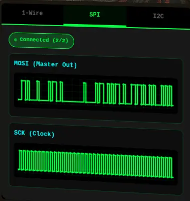
SPI
-
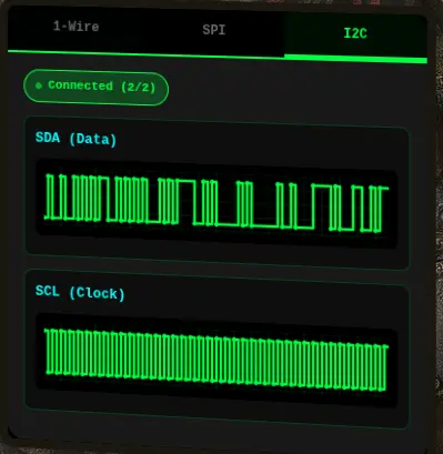
I2C
Enumeration
Let's figure out how the robot is getting those signals by looking at the source code in browser DevTools.
At the end of the HTML source is a large inline <script> block that handles all the signal processing.
There are five (5) wires:
  // Signal data storage for each wire
  const signalData = {
      'dq': [],
      'mosi': [],
      'sck': [],
      'sda': [],
      'scl': []
  };
The wires are associated to each tab through this mapping:
  // Wire to protocol mapping
  const wireToProtocol = {
      'dq': '1wire',
      'mosi': 'spi',
      'sck': 'spi',
      'sda': 'i2c',
      'scl': 'i2c'
  };
  // Helper function to get wires for a protocol
  function getProtocolWires(protocol) {
      const protocolWires = {
          '1wire': ['dq'],
          'spi': ['mosi', 'sck'],
          'i2c': ['sda', 'scl']
      };
      return protocolWires[protocol] || [];
  }
Each wire is connected to the protocol using a dedicated WebSocket endpoint /wire/{wireName}:
  // Connect to a specific wire
  function connectWire(wireName, protocolName) {
      if (connections[wireName]) {
          addLog(protocolName, `Already connected to ${wireName}`);
          return;
      }

      initCanvas(wireName);

      const proto = location.protocol === 'https:' ? 'wss' : 'ws';
      const host = location.host || location.hostname; // includes port if present in current URL
      const ws = new WebSocket(`${proto}://${host}/wire/${wireName}`);
      connections[wireName] = ws;

      ws.onopen = () => {
          updateStatus(protocolName);
          addLog(protocolName, `Connected to ${wireName}`);
      };

      ws.onmessage = (event) => {
          try {
              const data = JSON.parse(event.data);

              if (data.type === 'welcome') {
                  addLog(protocolName, `Server: ${data.message}`);
                  return;
              }

              if (data.line && typeof data.v !== 'undefined') {
                  updateSignal(data.line, data.v, data.t);
                  updateFrameCount(data.line);
              }
          } catch (e) {
              console.error('Error parsing message:', e);
          }
      };

      ws.onerror = (error) => {
          console.error(`WebSocket error on ${wireName}:`, error);
          addLog(protocolName, `Error on ${wireName}`);
      };

      ws.onclose = () => {
          delete connections[wireName];
          updateStatus(protocolName);
          addLog(protocolName, `Disconnected from ${wireName}`);
      };
  }
In the message handler, there is logic for the welcome message and additional logic for the rest of the data that updates the signal with three fields:
  if (data.line && typeof data.v !== 'undefined') {
    updateSignal(data.line, data.v, data.t);
    updateFrameCount(data.line);
  }
line— the wire namev— the value (0 or 1)t— the timestamp
WebSocket Endpoints
In the Network tab of the DevTools, we can confirm all the WebSocket endpoints:
| Protocol | Wire Name | WebSocket endpoint |
|---|---|---|
| 1-Wire | dq |
wss://signals.holidayhackchallenge.com/wire/dq |
| SPI | mosi |
wss://signals.holidayhackchallenge.com/wire/mosi |
sck |
wss://signals.holidayhackchallenge.com/wire/sck |
|
| I2C | sda |
wss://signals.holidayhackchallenge.com/wire/sda |
scl |
wss://signals.holidayhackchallenge.com/wire/scl |
We can also confirm the format of the messages.
1-Wire Protocol and Message Format
1-Wire Background
1-Wire is a protocol developed by Dallas Semiconductor that uses pulse-width encoding to transmit data over a single wire.
The key to decoding it is measuring how long the signal stays LOW:
- Short LOW pulse (1-15 time units) = 1.
- Long LOW pulse (~60 time units) = 0.
- Very long LOW pulses (150+) = reset/presence signals (skip these).
- Bits are transmitted LSB-first, i.e., need to reverse each group of 8 bits to get the correct byte value.
1-Wire Messages (dq wire)
{"type":"welcome","wire":"dq","message":"Connected to dq wire. Broadcasting continuously every 2000ms..."}
{"line":"dq","t":0,"v":1,"marker":"idle"}
{"line":"dq","t":1,"v":0,"marker":"reset"}
{"line":"dq","t":481,"v":1}
{"line":"dq","t":551,"v":0,"marker":"presence"}
{"line":"dq","t":701,"v":1}
{"line":"dq","t":941,"v":0}
{"line":"dq","t":1001,"v":1}
{"line":"dq","t":1011,"v":0}
{"line":"dq","t":1071,"v":1}
[...]
SPI Protocol and Message Format
SPI Background
SPI (Serial Peripheral Interface) uses separate clock and data lines. For this challenge, there is:
sck- the clock signalmosi- the data signal (Master Out, Slave In)
To decode SPI:
- Sample the MOSI data line on each rising edge of SCK (when clock goes 0→1).
- Bits are MSB-first (most significant bit first).
- XOR decrypt with the given key from the decoded 1-Wire message.
SPI Messages (mosi wire)
{"type":"welcome","wire":"mosi","message":"Connected to mosi wire. Broadcasting continuously every 2000ms..."}
{"line":"mosi","t":4880000,"v":0,"marker":"data-bit"}
{"line":"mosi","t":4890000,"v":1,"marker":"data-bit"}
{"line":"mosi","t":4900000,"v":0,"marker":"data-bit"}
{"line":"mosi","t":4910000,"v":0,"marker":"data-bit"}
{"line":"mosi","t":4920000,"v":0,"marker":"data-bit"}
{"line":"mosi","t":4930000,"v":0,"marker":"data-bit"}
{"line":"mosi","t":4940000,"v":1,"marker":"data-bit"}
{"line":"mosi","t":4950000,"v":1,"marker":"data-bit"}
{"line":"mosi","t":4960000,"v":0,"marker":"data-bit"}
{"line":"mosi","t":4970000,"v":0,"marker":"data-bit"}
{"line":"mosi","t":4980000,"v":0,"marker":"data-bit"}
{"line":"mosi","t":4990000,"v":0,"marker":"data-bit"}
{"line":"mosi","t":5000000,"v":1,"marker":"data-bit"}
[...]
SPI Messages (sck wire)
{"type":"welcome","wire":"sck","message":"Connected to sck wire. Broadcasting continuously every 2000ms..."}
{"line":"sck","t":605000,"v":1,"marker":"sample"}
{"line":"sck","t":610000,"v":0}
{"line":"sck","t":615000,"v":1,"marker":"sample"}
{"line":"sck","t":620000,"v":0}
{"line":"sck","t":625000,"v":1,"marker":"sample"}
{"line":"sck","t":630000,"v":0}
{"line":"sck","t":635000,"v":1,"marker":"sample"}
{"line":"sck","t":640000,"v":0}
{"line":"sck","t":645000,"v":1,"marker":"sample"}
{"line":"sck","t":650000,"v":0}
{"line":"sck","t":655000,"v":1,"marker":"sample"}
{"line":"sck","t":660000,"v":0}
{"line":"sck","t":665000,"v":1,"marker":"sample"}
{"line":"sck","t":670000,"v":0}
{"line":"sck","t":675000,"v":1,"marker":"sample"}
{"line":"sck","t":680000,"v":0}
{"line":"sck","t":685000,"v":1,"marker":"sample"}
{"line":"sck","t":690000,"v":0}
[...]
I2C Protocol and Message Format
I2C Background
I2C (Inter-Integrated Circuit) is another clock-and-data protocol, using:
scl- the clock signalsda- the data signal
Like SPI, you sample SDA on the rising edge of SCL, and bits are MSB-first. However, I2C has additional complexity:
- The first byte of each transaction is the address byte:
(7-bit address << 1) | R/W bit. - Every 9th bit is an ACK bit that must be skipped when extracting data.
- The target address is
0x3C.
I2C Messages (sda wire)
{"type":"welcome","wire":"sda","message":"Connected to sda wire. Broadcasting continuously every 2000ms..."}
{"line":"sda","t":0,"v":1,"marker":"bus-idle"}
{"line":"sda","t":2000,"v":0,"marker":"start"}
{"line":"sda","t":4000,"v":1,"marker":"address-bit","byteIndex":0,"bitIndex":0,"type":"address"}
{"line":"sda","t":14000,"v":0,"marker":"address-bit","byteIndex":0,"bitIndex":1,"type":"address"}
{"line":"sda","t":24000,"v":0,"marker":"address-bit","byteIndex":0,"bitIndex":2,"type":"address"}
{"line":"sda","t":34000,"v":1,"marker":"address-bit","byteIndex":0,"bitIndex":3,"type":"address"}
{"line":"sda","t":44000,"v":0,"marker":"address-bit","byteIndex":0,"bitIndex":4,"type":"address"}
{"line":"sda","t":54000,"v":0,"marker":"address-bit","byteIndex":0,"bitIndex":5,"type":"address"}
{"line":"sda","t":64000,"v":0,"marker":"address-bit","byteIndex":0,"bitIndex":6,"type":"address"}
{"line":"sda","t":74000,"v":0,"marker":"address-bit","byteIndex":0,"bitIndex":7,"type":"address"}
{"line":"sda","t":84000,"v":0,"marker":"ack-bit","byteIndex":0,"type":"ack"}
{"line":"sda","t":94000,"v":1,"marker":"ack-release","byteIndex":0,"type":"ack"}
{"line":"sda","t":94000,"v":0,"marker":"data-bit","byteIndex":1,"bitIndex":0,"type":"data"}
{"line":"sda","t":104000,"v":1,"marker":"data-bit","byteIndex":1,"bitIndex":1,"type":"data"}
{"line":"sda","t":114000,"v":0,"marker":"data-bit","byteIndex":1,"bitIndex":2,"type":"data"}
{"line":"sda","t":124000,"v":1,"marker":"data-bit","byteIndex":1,"bitIndex":3,"type":"data"}
{"line":"sda","t":134000,"v":0,"marker":"data-bit","byteIndex":1,"bitIndex":4,"type":"data"}
{"line":"sda","t":144000,"v":1,"marker":"data-bit","byteIndex":1,"bitIndex":5,"type":"data"}
{"line":"sda","t":154000,"v":1,"marker":"data-bit","byteIndex":1,"bitIndex":6,"type":"data"}
{"line":"sda","t":164000,"v":0,"marker":"data-bit","byteIndex":1,"bitIndex":7,"type":"data"}
{"line":"sda","t":174000,"v":0,"marker":"ack-bit","byteIndex":1,"type":"ack"}
{"line":"sda","t":184000,"v":1,"marker":"ack-release","byteIndex":1,"type":"ack"}
[...]
I2C Messages (scl wire)
{"line":"scl","t":64000,"v":0,"marker":"address-hold","byteIndex":0,"bitIndex":5,"type":"address"}
{"line":"scl","t":69000,"v":1,"marker":"address-sample","byteIndex":0,"bitIndex":6,"type":"address"}
{"line":"scl","t":74000,"v":0,"marker":"address-hold","byteIndex":0,"bitIndex":6,"type":"address"}
{"line":"scl","t":79000,"v":1,"marker":"address-sample","byteIndex":0,"bitIndex":7,"type":"address"}
{"line":"scl","t":84000,"v":0,"marker":"address-hold","byteIndex":0,"bitIndex":7,"type":"address"}
{"line":"scl","t":89000,"v":1,"marker":"ack-sample","byteIndex":0,"type":"ack"}
{"line":"scl","t":94000,"v":0,"marker":"ack-hold","byteIndex":0,"type":"ack"}
{"line":"scl","t":99000,"v":1,"marker":"data-sample","byteIndex":1,"bitIndex":0,"type":"data"}
{"line":"scl","t":104000,"v":0,"marker":"data-hold","byteIndex":1,"bitIndex":0,"type":"data"}
{"line":"scl","t":109000,"v":1,"marker":"data-sample","byteIndex":1,"bitIndex":1,"type":"data"}
{"line":"scl","t":114000,"v":0,"marker":"data-hold","byteIndex":1,"bitIndex":1,"type":"data"}
{"line":"scl","t":119000,"v":1,"marker":"data-sample","byteIndex":1,"bitIndex":2,"type":"data"}
{"line":"scl","t":124000,"v":0,"marker":"data-hold","byteIndex":1,"bitIndex":2,"type":"data"}
{"line":"scl","t":129000,"v":1,"marker":"data-sample","byteIndex":1,"bitIndex":3,"type":"data"}
{"line":"scl","t":134000,"v":0,"marker":"data-hold","byteIndex":1,"bitIndex":3,"type":"data"}
{"line":"scl","t":139000,"v":1,"marker":"data-sample","byteIndex":1,"bitIndex":4,"type":"data"}
{"line":"scl","t":144000,"v":0,"marker":"data-hold","byteIndex":1,"bitIndex":4,"type":"data"}
{"line":"scl","t":149000,"v":1,"marker":"data-sample","byteIndex":1,"bitIndex":5,"type":"data"}
{"line":"scl","t":154000,"v":0,"marker":"data-hold","byteIndex":1,"bitIndex":5,"type":"data"}
{"line":"scl","t":159000,"v":1,"marker":"data-sample","byteIndex":1,"bitIndex":6,"type":"data"}
{"line":"scl","t":164000,"v":0,"marker":"data-hold","byteIndex":1,"bitIndex":6,"type":"data"}
{"line":"scl","t":169000,"v":1,"marker":"data-sample","byteIndex":1,"bitIndex":7,"type":"data"}
{"line":"scl","t":174000,"v":0,"marker":"data-hold","byteIndex":1,"bitIndex":7,"type":"data"}
{"line":"scl","t":179000,"v":1,"marker":"ack-sample","byteIndex":1,"type":"ack"}
{"line":"scl","t":184000,"v":0,"marker":"ack-hold","byteIndex":1,"type":"ack"}
[...]
High-Level Strategy
The goal is to get the reading from the I2C device at address 0x3C. Using the provided WebSocket endpoints, this is the high-level strategy:
- Capture and analyze the 1-Wire signal to find information that helps read the SPI signal.
- Capture and analyze the SPI signal to find information that helps read the I2C signal.
- Capture and analyze the I2C signal to decrypt the final information and solve the challenge.
Solution
Stage 1: 1-Wire Data
1-Wire Data Capture
Let's capture 1-Wire signal data into a dq.csv file using the 1-wire_capture.py Python script.
[*] Collected 1000/10000
[*] Collected 2000/10000
[*] Collected 3000/10000
[*] Collected 4000/10000
[*] Collected 5000/10000
[*] Collected 6000/10000
[*] Collected 7000/10000
[*] Collected 8000/10000
[*] Collected 9000/10000
[*] Collected 10000/10000
[+] Done. Collected 10000 messages into dq.csv
The CSV data captured from the Python script looks like:
line,t,v
[...]
dq,32307,1
dq,32371,0
dq,32431,1
dq,32441,0
dq,32501,1
dq,32511,0
dq,32517,1
dq,32581,0
dq,32587,1
dq,32651,0
dq,32657,1
dq,32721,0
dq,32727,1
dq,32791,0
dq,32851,1
dq,32871,1
dq,0,1
dq,1,0
dq,481,1
dq,551,0
dq,701,1
dq,941,0
dq,1001,1
dq,1011,0
dq,1071,1
dq,1081,0
dq,1087,1
dq,1151,0
dq,1157,1
dq,1221,0
dq,1281,1
dq,1291,0
dq,1351,1
dq,1361,0
dq,1367,1
dq,1431,0
dq,1437,1
dq,1501,0
dq,1561,1
[...]
1-Wire Data Analyze
From looking at the data:
dqis the 1-Wire data line.tis the timestamp (looks like microseconds or clock ticks).vis the logic level.- A low pulse is always:
-
1→0(falling edge). - followed by0→1(rising edge). - Each bit value is encoded by how long the line stays LOW.
Let's manually compute a few low pulse durations to identify any patterns:
| Falling edge | Rising edge | Low duration |
|---|---|---|
| 1 → 0 @ t=1 | 0 → 1 @ t=481 | 480 |
| 1 → 0 @ t=551 | 0 → 1 @ t=701 | 150 |
| 1 → 0 @ t=941 | 0 → 1 @ t=1001 | 60 |
| 1 → 0 @ t=1011 | 0 → 1 @ t=1071 | 60 |
| 1 → 0 @ t=1081 | 0 → 1 @ t=1087 | 6 |
| 1 → 0 @ t=1151 | 0 → 1 @ t=1157 | 6 |
Clear clusters emerge from this initial analysis:
- ~480 → very long → RESET (once at the very beginning)
- ~150 → long → start marker / presence / framing / SYNC (once)
- ~60 → medium → bit 0
- ~6 → short → bit 1
After the initial sync, the stream is simply NRZ (Non-Return-to-Zero) bits encoded by pulse width:
- Short low (6) = 1
- Longer low (60) = 0
Note
NRZ (Non-Return-to-Zero) bits are a binary signaling method in digital communications where voltage levels remain high for a logic '1' and low for a logic '0', without returning to a neutral voltage in between. Instead of having a "rest" period between each bit, the signal stays high or low for the entire duration of the bit period.
1-Wire Data Decode
Applying that logic to the captured pulses, let's decode bits:
So, from pulse #3 onward, every pulse is a bit.Let's put everything together, assemble bytes (LSB-first) by taking groups of 8 and convert into ASCII:
def bits_to_bytes_lsb(bits):
    out = []
    for i in range(0, len(bits) - 7, 8):
        byte = 0
        for b in range(8):
            byte |= bits[i + b] << b
        out.append(byte)
    return out
The 1-wire_decoder.py Python script provides a staged decoding pipeline that separates signal parsing, pulse extraction, bit reconstruction, and byte decoding, allowing iterative validation at each layer.
- The script detects if there are multiple RESET instances to identify multiple frames.
- Since the pulse widths are clustered into two ranges (~6µs and ~60µs), it uses tolerant thresholds instead of exact matching to account for jitter that could be present in real hardware behavior. This makes the solution portable and not specific to this dataset.
- The output provides a histogram to show the thresholds visually and the protocol structure (RESET, SYNC, data).
Running the decoder Python script with the dq.csv file, we get this output:
[*] Pulse distribution: Counter({60: 266, 6: 190, 480: 1, 150: 1})

[+] Detected 1 frame(s)

[*] --- Frame 0 ---
[*] Bytes: [204, 114, 101, 97, 100, 32, 97, 110, 100, 32, 100, 101, 99, 114, 121, 112, 116, 32, 116, 104, 101, 32, 83, 80, 73, 32, 98, 117, 115, 32, 100, 97, 116, 97, 32, 117, 115, 105, 110, 103, 32, 116, 104, 101, 32, 88, 79, 82, 32, 107, 101, 121, 58, 32, 105, 99, 121]
[*] Hex:   ['0xcc', '0x72', '0x65', '0x61', '0x64', '0x20', '0x61', '0x6e', '0x64', '0x20', '0x64', '0x65', '0x63', '0x72', '0x79', '0x70', '0x74', '0x20', '0x74', '0x68', '0x65', '0x20', '0x53', '0x50', '0x49', '0x20', '0x62', '0x75', '0x73', '0x20', '0x64', '0x61', '0x74', '0x61', '0x20', '0x75', '0x73', '0x69', '0x6e', '0x67', '0x20', '0x74', '0x68', '0x65', '0x20', '0x58', '0x4f', '0x52', '0x20', '0x6b', '0x65', '0x79', '0x3a', '0x20', '0x69', '0x63', '0x79']
[+] ASCII: .read and decrypt the SPI bus data using the XOR key: icy
1-Wire Data Answer
The 1-Wire bus data decrypted message indicates that the SPI bus data can be decrypted using the XOR key icy.
Stage 2: SPI Data
SPI Data Capture
Let's capture SPI signal data into mosi.json and sck.json files using the spi_capture.py Python script.
[+] Connecting to MOSI at wss://signals.holidayhackchallenge.com/wire/mosi ...
[+] Connecting to SCK at wss://signals.holidayhackchallenge.com/wire/sck ...
[+] Connected to MOSI. Waiting for first idle-low...
[+] Connected to SCK. Waiting for first idle-low...
[+] First idle-low for SCK detected — starting capture
[+] Second idle-low for SCK detected — finishing capture
[+] Saved SCK capture to sck.json
[+] First idle-low for MOSI detected — starting capture
[+] Second idle-low for MOSI detected — finishing capture
[+] Saved MOSI capture to mosi.json
[+] Both captures complete.
SPI Data Analyze
- There are only two lines:
SCK(the clock signal).MOSI(the data signal).
- There is no
CSline; hence, frame boundaries rely on idle markers. - Clock idle state is LOW (CPOL = 0).
- Sampling edge is rising edge (CPHA = 0).
- Bit order is MSB first.
- XOR key is
icy(from Stage 1).
From the captured sck.json file:
- Idle-low is SPI Mode 0 (CPOL=0).
- The marker "sample" appears on SCK = 1.
- The clock period is constant:
- There is a rising edge every 10,000.
- A sample occurs at mid–high phase: t = 5k, 15k, 25k, ...
This means:
- Sample
MOSIwhenSCKgoes high. - Each "sample" marker corresponds to one SPI bit.
MOSImust be sampled at the same timestamps.
SPI Data Decode
The spi_decoder.py Python script helps automate the decoding process with the following steps:
- Load raw signals from both JSON files.
- Extract
SCKsample timestamps to determine the clock rising edges (0→1transitions). - At each
SCKsample time, read the correspondingMOSIvalue. - Group bits into bytes (MSB first).
- XOR decrypt with key
icy. - Extract human-readable message.
Running the decoder Python script with the sck.json and mosi.json files, we get this output:
[+] Loaded 800 SCK sample points
[+] Extracted 800 SPI bits
[+] Assembled 100 bytes

[*] [Hex]
1b 06 18 0d 43 18 07 07 59 0d 06 1a 1b 1a 09 1d 43 0d 01 06 59 20 51 3a 49 01 0c 1a 43 1d 08 17 18 49 16 0a 00 0d 1e 49 17 11 0c 43 21 26 31 59 02 06 00 53 43 1b 08 0d 18 07 19 18 47 43 0d 01 06 59 1d 06 14 19 06 0b 08 17 0c 1b 06 59 1a 06 17 1a 0c 0b 49 02 1d 0d 11 1c 1a 10 59 00 10 59 59 1b 4a 2a

[*] [Raw ASCII]
....C...Y.......C...Y Q:I...C....I.....I...C!&1Y...SC.......GC...Y...........Y......I.......Y..YY.J*

[+] [Decrypted ASCII]
read and decrypt the I2C bus data using the XOR key: bananza. the temperature sensor address is 0x3C
SPI Data Answer
The SPI data bus decrypted message indicates that the I2C bus data can be decrypted using the XOR key bananza.
Stage 3: I2C Data
I2C Data Capture
Let's capture I2C signal data into scl.json and sda.json files using the i2c_capture.py Python script.
The script captures I2C traffic by leveraging timestamp resets (t == 0) as frame boundaries, buffering a complete transaction for both SDA and SCL lines, and preserving timing relationships for accurate clock-driven decoding.
[+] Connecting to SDA at wss://signals.holidayhackchallenge.com/wire/sda ...
[+] Connecting to SCL at wss://signals.holidayhackchallenge.com/wire/scl ...
[+] Connected to SDA. Waiting for first timestamp=0...
[+] Connected to SCL. Waiting for first timestamp=0...
[+] First timestamp=0 for SCL detected — starting capture
[+] First timestamp=0 for SDA detected — starting capture
[+] Second timestamp=0 for SCL detected — finishing capture
[+] Second timestamp=0 for SDA detected — finishing capture
[+] Saved 502 packets to scl.json
[+] Saved 286 packets to sda.json
[+] Both captures complete.
I2C Data Analyze
- There are only two wires:
SCL(the clock signal).SDA(the data signal).
- The idle state for both lines is high.
- Need to detect START condition:
SDA:1→0whileSCL=1
- Need to detect STOP condition:
SDA:0→1whileSCL=1
- For each transaction:
- Need to sample
SDAon rising edge ofSCL. - Each byte is 8 bits (MSB first).
- Every 9th bit is
ACKand should be ignored/skipped.
- Need to sample
- First byte is equal to address + R/W bit.
- Need to find first byte equal to
0x3Cto locate the start of the relevant data. - XOR key is
bananza(from Stage 2).
I2C Data Decode
The SDA capture already has clean semantic markers:
startaddress-bitdata-bitack-bitstop
This makes the decoder much simpler than raw edge correlation for clock-edge detection. We can safely ignore SCL entirely and trust the marker, byteIndex, and bitIndex fields.
The i2c_decoder.py Python script helps automate the decoding process with the following steps:
- Load raw
SDAevents. - Perform bit reconstruction.
- Perform byte reconstruction.
- Parse each transaction.
- Filter for address
0x3C. - Extract payload.
- XOR decrypt with key
bananza. - Extract temperature value.
Running the decoder Python script with the sda.json file, we get this output:
[+] Decoded 4 I2C transactions

[*] TX 0: addr=0x48 data=[86, 84, 75]
[*] TX 1: addr=0x3C data=[81, 83, 64, 89, 90]
[*] TX 2: addr=0x51 data=[83, 81, 95, 82, 78, 18, 49, 3]
[*] TX 3: addr=0x29 data=[86, 84, 94, 65, 2, 15, 25]

[*] [Raw ASCII]
QS@YZ

[*] [Hex]
33 32 2e 38 34

[+] [Decrypted ASCII]
32.84
I2C Data Answer
The I2C data bus decrypted message indicates that the temperature of the device is 32.84.
Outro
Evan Booth
Nice work! You cracked that signal encoding like a pro.
Turns out the weirdness had a method to it after all - just like most of my builds!
Files
| File | Description |
|---|---|
1-wire/1-wire_capture.py |
Python script to capture 1-Wire DQ signal data via WebSocket |
1-wire/dq.csv |
CSV file with captured 1-Wire DQ signal data |
1-wire/1-wire_decoder.py |
Python script to decode 1-Wire frames from the CSV file |
spi/spi_capture.py |
Python script to capture SPI MOSI/SCK signals via WebSocket |
spi/mosi.json |
JSON file with captured SPI MOSI signal data |
spi/sck.json |
JSON file with captured SPI SCK signal data |
spi/spi_decoder.py |
Python script to decode SPI frames from MOSI/SCK JSON files |
i2c/i2c_capture.py |
Python script to capture I2C SDA/SCL signals via WebSocket |
i2c/sda.json |
JSON file with captured I2C SDA signal data |
i2c/scl.json |
JSON file with captured I2C SCL signal data |
i2c/i2c_decoder.py |
Python script to decode I2C frames from the SDA JSON file |
References
ctf-techniques/hardware/— 1-Wire, SPI, and I2C protocol capture and decoding techniquesctf-techniques/crypto/— XOR decryption (repeating-key)
Navigation
| ← Schrödinger's Scope | Free Ski → |